 Procedural Materials
The Procedures tree combines one or more materials using a set of rules for how the materials interact. The tree displays the components used to create the material and lets you add components. For simple materials, there will be only one component in the list: Base.
Each procedure combines two "child" materials using a specific method. Each of these child materials can in turn consist of a procedure, combining two children of its own. In this way, extremely elaborate materials can be built from simpler constituents. Procedures for combining materials include:
To add a procedure
- Right-click anywhere in the Procedures window.
- On the menu, click a procedure type.
To remove a procedure
- In the Procedures window, right-click the procedure name.
- On the menu, click Remove.
Base
This is the basic simple material with no layers. This is the default procedure.
Angular Blend
Many materials change color, reflection, or transparency based on the angle the material is viewed. The Angular Blend procedure blends between two materials based on the angle of view to the surface of the object.
 The Angular Blend procedure blends between two different materials to create special effects. The two layers in the procedure are the Inner and the Outer Layer.
Inner
From 0 degrees from the viewpoint to the Start angle, the Inner component will show completely. Think of this as a base material.
Outer
From the Stop angle to 90 degrees from the view, the Outer component will be the only material showing. Think of this as a coating.
Start angle
The angle from the viewpoint at which the Outer component material starts.
Stop angle
The angle from the viewpoint at which the Outer component material stops. Between the Start Angle and the Stop angle, the Inner and the Outer components blend.
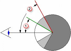
In the illustration below, the Start angle is 30 degrees (which in rendering translates to the the green circle on the right) and the Stop angle
 is 60 degrees (in the rendering that translates to the red circle).
The image at the right shows the the Inner material as white, and the Outer material as black.
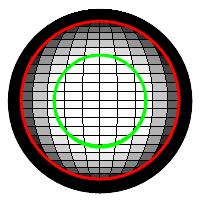
- Between 0 and 30 degrees from the viewpoint, you see white.
- Between 30 and 60 degrees from the viewpoint, you see a gradient from white to black.
- Between 60 and 90 degrees from the viewpoint, you see black.
Blend
The Blend procedure combines two base components and controls the proportions of each. All of the standard library wood materials use a Blend procedure to change the finish of the wood from clear matte to dark shiny.
 Blends work well changing an entire material definition by adding an overall color to a base patterned material.
Blend
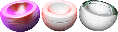
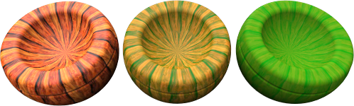
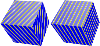
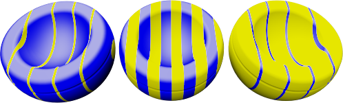
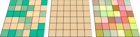
Varies the percentage of each component material used in the final material. For instance, the material below shows a blend between the striped material and solid green color. The left image shows the slider to the left, showing a strong stripe material and weak green. The middle image show the slider in the middle and a blended 50% striped and 50% green color. The right image shows the slider to the right, showing a weak striped material with a strong green material.
Use image
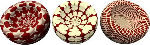
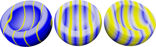
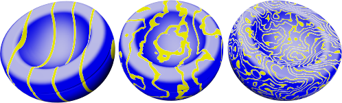
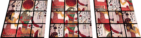
An image can be used to control how two materials will interact. When using a Bitmap image the grayscale values of the pixels define where two component materials will blend. Use a grayscale image map to mediate between the first and second components. The First component will be placed where there is black in the bitmap pattern, and the Second component will be placed where there is white in the bitmap pattern.
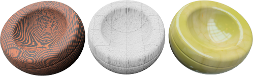
In the image, the same materials are used for the first and second components, but the blend is controlled by three different bitmaps.
 The resolution of the mask bitmap affects the material quality. Higher resolution bitmaps allow a viewpoint closer to the material with fewer quality issues, but they also use more memory.
Use Alpha channel
If the image has an alpha channel, this can be used instead of the bitmap grayscale to determine where the colors blend.
Reverse
The First component will be placed where there is white in the bitmap pattern, and the Second component will be placed where there is black in the bitmap pattern.
Tiles
The scale of the material is independent of the resolution of the bitmap used to define it. To scale the material correctly, decide how large an area in real units one copy of the bitmap represents. If the bitmap represents the height of six 4-unit tiles and the length represents twelve 4-unit tiles, the scale is 48 units in the x-direction and 24 units in the y-direction. This stretches the bitmap to the proper size for the pattern.
Width
The width in pixels of a single instance of the image.
Height
The height in pixels of a single instance of the image.
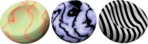
Granite
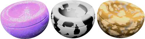
Creates a 3-D material with solid pockets of a second material embedded in the Base component. The Granite procedure combines a randomly distributed Spot component in a Base component. The Granite procedure defines how the Base and Spot components combine. Granite procedures can be used for a variety of different materials including rust, sparkly plastic, and other randomly spotted materials.
Base/Spot
The Base and Spot components are two materials. Their properties are specified in the same way as any material.
X/Y/Z Scale
Changes the absolute size of the pattern in the x-, y-, and z-directions.
Lock
Maintains the ratio between the X Scale, Y Scale, and Z Scale.
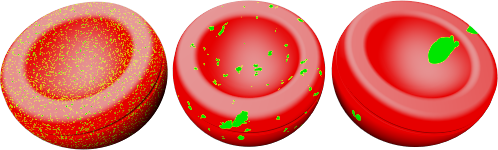
Density
A fraction of the whole pattern. Increasing this setting increases the relative size of the spots.
Blend
Blurs the boundaries between the components.
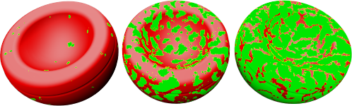
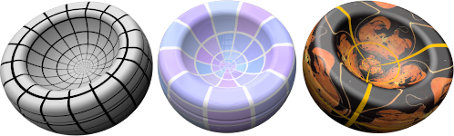
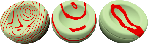
Marble
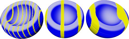
Creates alternating slabs of Base and Vein components. The Marble procedure defines how the Base and Vein components combine. The slabs are infinitely large, and the orientation of the object affects the way the slabs are oriented with respect to the object.
Texture mapping for the objects controls the orientation of the material on the object.
 No texture mapping (left). With texture mapping (right).
Base/Vein
The Base and Vein components are two materials. Their properties are specified in the same way as any material.
X/Y/Z Scale
Changes the absolute size of the pattern in the x-, y-, and z-directions.
Lock
Maintains the ratio between the X Scale, Y Scale, and Z Scale.
Vein Width
Alters the relative size of the slabs to each other. Vein Width is a fraction of the distance from one Base stripe to the next. Values range from 0 (zero) for no Vein component to 1 for no Base component.
Blend
Blurs the boundaries between the components.
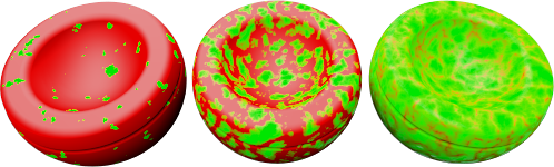
Turbulence
Produces the swirled appearance by causing the alternating components to bend and twist.
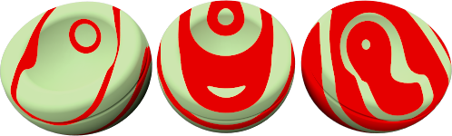
Veneer
Causes the material to appear as a planar pattern on the surfaces of the object instead of cutting through the object.
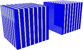 Veneer (left), normal (right).
Tile
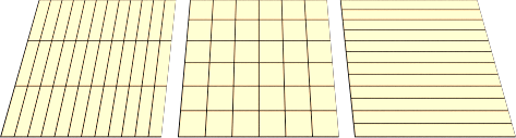
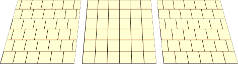
Tile is a 2-D material. Texture mapping for the objects controls the orientation of the material on the object. The Tile material combines a Base component and a Joint component. Each of these materials can also include any other material.
 Scale tile differently in each direction for special effects. For example, use a tile material that is extremely long in one direction to create siding materials.
Tile
Sets the overall tile size. The width and height sizes can be set independently.
Width/Height
Specifies the width and height of the tiles.
Lock
Maintains the ratio between the Width and Height.
Joint
Specifies the size of the joint material.
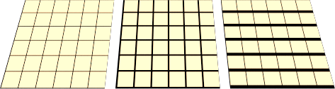
Horizontal joint/Vertical joint
Specifies the width and height of the joint material.
Lock
Maintains the ratio between the Horizontal and Vertical joint sizes.
Offset
Provides a relative horizontal offset per vertical tile. For example, use a setting of .5 to produce a standard running bond. This allows modeling of material such as marble tile, without the effect of having the entire floor hewn from the same block of marble.
Vary Tiles
Add randomness to the material color for each tile. This makes it possible to model material such as non-uniform bricks.
R/G/B
Modifies the red, green, and blue color components. This will slightly vary the base material of each tile randomly.
X/Y/Z
Offsets the material from the world origin for each tile randomly. Do this if a seam that marks the beginning of the material appears in an inappropriate place.
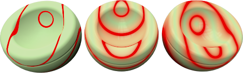
Wood
Wood consists of concentric cylinders of alternating Base and Ring components. The Wood settings define how the Base and Ring components combine.
Use this method to create wood materials if objects are not closely viewed. If detailed wood is needed, use a Texture material to do wood. If the viewpoint is not close to the wood, a solid color can be used to take the place of wood without sacrificing image quality. This allows faster rendering. An additional advantage of using a wood material is that when rendering different sides of an object, the wood grain will look correct. End grain will show on the ends and parallel grain will show on the sides of an object.
Base/Ring
The Base and Ring components are two materials. Their properties are specified in the same way as any material.
X/Y/Z Scale
Changes the absolute size of the pattern in the x-, y-, and z-directions.
Lock
Maintains the ratio between the X Scale, Y Scale, and Z Scale.
Ring Width
A fraction of the distance between one Base stripe and the next. Values range from 0 (zero) for no Ring component to 1 for no Base component.
Blend
Blurs the boundaries between the components.
Turbulence
Produces the swirled appearance by causing the alternating components to bend and twist.
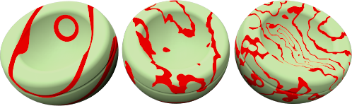
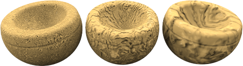
Veneer
Causes the material to appear as a planar pattern on the surfaces of the object instead of cutting through the object.
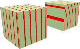 Veneer (left), normal (right).