 Material Image Properties
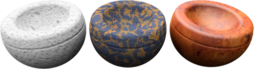
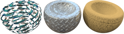
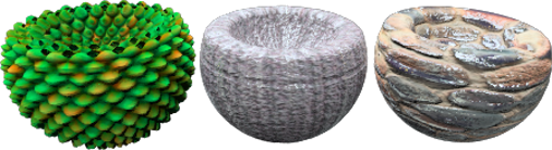
Materials can be created from images. Scan photographs and real materials like wallpaper and carpet, create patterns in a paint program, or use images from other bitmap sources.
Imagine that the material stretches infinitely in all directions in space. The material becomes visible only where an object passes through it. Patterns are repeated infinitely (tiled) in four directions at a specified scale.
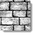
Small images that can be seamlessly tiled tend to work best. If the bitmap does not tile well, use the option to mirror the tiles. This guarantees matched edges.
Note: To make a bitmap image cover only part of the object (like a label on a wine bottle or a logo on a product), use the Decal feature instead.
Image maps can be used many ways. A common method is to use a picture of a real-world material as the materials color.
Name
Image Textures can be named. This name is used by the Texture library of the RDK and has no real impact on Flamingo.
Flamingo Image
Image preview
Displays a preview of the selected image file. Hold the mouse over the image to see a pop-up of the image file name. Click on the image to select a different image.
Image resolution
Displays the resolution in pixels of the current image file.
Tiles
Image maps used in material definitions are always repeated (tiled). These settings specify how large each instance (tile) will be in current model units.
Width/Height
Sets the tile size in model units.
Lock
Maintains the ratio between the Width and Height.
Masking
Obscures portions of the image based on either a color value or an alpha channel stored in the image. This allows textures to have complex shaped boundaries and create complex effects such as holes in a surface.
In this example, an image with an alpha-channel background is placed as a decal on a rectangular surface. Masking for materials works the same.
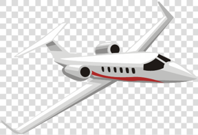
 Original decal image. The gray checkered area represents the image alpha channel.
Masking information can come from three sources in the bitmap:
None
With no masking, the image obscures the underlying material. Masking allows the material to show through the image where the alpha channel or masking color exists. The material assigned to a planar surface in this example has a red base color.
 Without masking (left) the image covers the surface, with masking (right), the red material shows through.
Alpha Channel
Uses the image’s alpha channel to define the masked area if one exists.
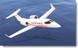
Original on the left. The gray checkered area represents the image alpha channel. On the right is the image over a water surface.
The alpha channel is a portion of each pixel’s data that is reserved for transparency information. Alpha channels create and store masks that let you isolate and protect parts of an image while you apply color changes, filters, or other effects to the rest of the image. Each pixel in an image is described as channels of data that define the mixture of the red, green, and blue (RGB) colors. The alpha channel is an 8-bit (256-level) grayscale representation of the image that masks the color of the underlying pixel. The value of the alpha mask determines the intensity of the pixel color. If the Alpha channel is 100%, the images pixel will be complete transparent. At other alpha strengths, the image pixels will blend with transparency.
Color
If alpha channel does not exist in an image, a color in the image can be specified as a mask. There is also a sensitivity number to make the mask more or less sensitive to a single specific color as a masked color. Selecting the Color option will activate the Color Dropper, Color Selector, and Sensitivity controls.
Color Dropper
Click to select the mask color from the bitmap. Click on the Color Dropper, then on the bitmap to pick the color. This control is only available when the Color option is selected.
Color
Use the Color Selector to set the main color. See the Color Selector  topic for details.
Sensitivity
The value indicates the size of the area around the color that is also masked. Must be greater than 0.0 for color masking to occur. This control is only available when the Color option is selected.
Blur
Partially masks pixels. The value determines the magnitude of partial masking around the masked color. This control is only available when the Color option is selected.
Reverse
Inverts the mask. Pixels that would have been masked are now included, and pixels once included are now masked.

Transparent
Makes the masked area of the underlying object transparent so other objects or the background behind the object can be seen through the object. Normally, the material of the object shows through in that area.
Transparent masking allows a more natural shadow and lets the background objects to show. The underlying material could simply be transparent, but sometimes it is useful to make the surface behind the decal transparent while keeping other areas of the surface opaque.

Show masked colors
Graphically displays the effects of masking as the parameters change. Use the Color Selector provided to select the display color of the masked pixels. Changing this color or the setting of the checkbox does not change the masked color. This is simply a graphical tool for editing the mask.

Mapping type
Images normally apply to the color channel. But there are other ways to use images. Images can be set as:
Standard
The image provides color and visual bump to the material. Use the Strength and Bump values to control how the bitmap will influence the material.
Color Strength
Determines how much the image map influences the material appearance. In the example below, the underlying material is magenta colored. The color strength increases until the underlying color is completely masked by the black and white texture.
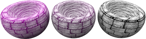 Color strength 0.2, 0.5, 1.0.
Bump Strength
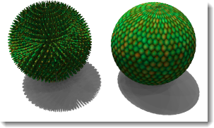
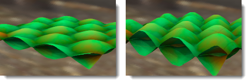
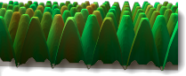
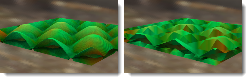
Simulates bumps and wrinkles on the surface of an object by perturbing the surface normals of the object. The underlying object is not changed. In the illustration, the material on the left uses displacement mapping, while the material on the right uses bump mapping set at its highest value. Using negative bump numbers will reverse the effect. The edge and shadow are smooth for the bump-mapped material. See: Wikipedia article: Bump mapping.
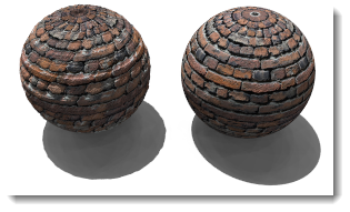 Bump strength, 0.5 (left) and 1.0 (right).
Normal
Fakes the lighting of bumps and dents without using more polygons to the render mesh. See: Wikipedia article: Normal mapping.
Normal maps work very similar to bump maps, in that they modify the normal of the surface. The effect is essentially the same as bump, but normal maps allow more control over the normal than a bump. A bump map uses the grey average of the RGB in a bitmap. The RGB of a normal map corresponds to the modification of the XYZ of the normal. Because the blue channel of the image controls the Z-direction of the normal, normal maps have a considerable blue color to them.
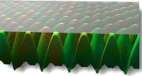
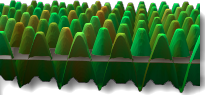
Displacement
This image map displaces the surface render mesh based on the color values in the image. The effect is a change in the actual geometric position of the surface. The displacement is often along the local surface normal. See: Wikipedia article: Displacement mapping.
Note: Use displacement mapping sparingly for small objects. Displacement increases rendering time considerably.
Height
The height of the highest point of displacement.
Offset
Sets the starting point of the displacement with reference to the surface normal. The displacement can take place completely outside, inside, or some ratio inside and outside the part.
 Z-offset = -1.0
 Z-offset = -0.5
 Z-offset = 0.0
Facet size
The size of the facets of the displacement mesh. This will increase the detail in the displacement, but also will increase rendering size and memory usage.
Flamingo Image Advanced
Normally a Flamingo Image will apply to the main color channel of a material. The Flamingo Advanced dialog specifies other channels that the bitmap can effect. These are used for very special effects.
Base color
This is the default setting. An image will effect the color of a material.
Specular color
This will affect the color of reflection channel based on the image color at that point.
Specular intensity
This will change the amount of reflection based on the grayscale of the image at that point. This is used often in Texture Sets as a Specular Map.
Highlight sharpness
This will adjust the sharpness vs blurriness of the highlight based on the grayscale value of the map at that point.
Highlight shape
Affects the shape of the highlight.
Transparency
This will affect the amount of transparency in the material based on the grayscale of the image.
Translucency
This will affect the amount of translucency in the material based on the grayscale of the image.
Attenuation
This will affect the amount of attenuation in the material based on the grayscale of the image.
Offsets X/Y
Offsets the material from the x- and y-axis.
Rotation
This will rotate the image map. Use to rotate the image 90 or 180 degrees if needed to reorient the image from its default rotation.